The Ethernet Version
II Frame Format
Introduction
The
following is a description of the frame format described
by the original Ethernet Version
II specification as released by DEC, Intel, and
Xerox. Like the 802.3 spec, the Version II spec defines
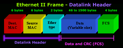
a Data Link Header consisting of 14 bytes (6+6+2)
of information, but the Version II spec does not specify
an LLC header.
Let's now
have a closer look at the frame format:

THE DATA LINK HEADER
Offset 0-5: The Destination Address
- The
first six bytes of an Ethernet frame make up the
Destination Address. The Destination Address
specifies to which adapter the data frame is being
sent. A Destination Address of all ones specifies a
Broadcast Message that is read in by all receiving
Ethernet adapters.
- The
first three bytes of the Destination Address are
assigned by the IEEE to the vendor of the adapter
and are specific to the vendor. See the
MAC
Address page for more information.
- The
Destination Address format is identical in all
implementations of Ethernet.
Offset 6-11: The Source Address
- The
next six bytes of an Ethernet frame make up the
Source Address. The Source Address specifies from
which adapter the message originated. Like the
Destination Address, the first three bytes specify
the vendor of the card.
- The
Source Address format is identical in all
implementations of Ethernet.
Offset 12-13: The Ethertype
-
Following the Source Address is a 2 byte field
called the Ethertype. The Ethertype is analogous to
the SAPs in the 802.3 frame in that it specifies the
memory buffer in which to place this frame.
An
interesting question arises when one considers the 802.3
and Version II frame formats: Both formats specify a 2
byte field following the source address (an Ethertype in
Version II, and a Length field in 802.3) -- How does a
driver know which format it is seeing, if it is
configured to support both?
The answer
is actually quite simple. All Ethertypes have a value
greater than 05DC hex, or 1500 decimal. Since the
maximum frame size in Ethernet is 1518 bytes, there is
no point in overlapping between Ethertypes and lengths.
If the field that follows the Source Address is greater
than O5DC hex, the frame is a Version II, otherwise it
is something else (either 802.3, 802.3 SNAP or Novell
Proprietary).

USER DATA AND FCS
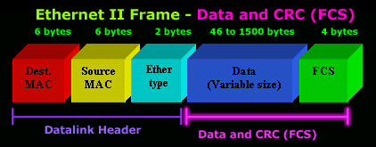
Data: 46-1500 Bytes
-
Following the Ethertype are 46 to 1,500 bytes of
data, generally consisting of upper layer headers
such as TCP/IP or IPX and then the actual user data.
FCS: Last 4 Bytes
- The
last 4 bytes that the adapter reads in are the Frame
Check Sequence or CRC. When the voltage on the wire
returns to zero, the adapter checks the last 4 bytes
it received against a checksum that it generates via
a complex polynomial. If the calculated checksum
does not match the checksum on the frame, the frame
is discarded and never reaches the memory buffers in
the station.
|
