|
The Three Stages
All switches
regardless of the brand and various enhancements they
carry, have something in common, it's the three stages
(sometimes 2 stages) they go through when powered up and
during operation. These are as follows:
-
Loop Avoidance (Optional)
Let's have
a look at them to get a better understanding!
Address Learning
When a
switch is powered on, the MAC filtering table is empty.
When a device transmits and an interface receives a
frame, the switch places the source address in the MAC
filtering table remembering the interface the device on
which it is located. The switch has no choice but to
flood the network with this frame because it has no idea
where the destination device is located.
If a device answers and sends a frame back, then the
switch will take the source address from that frame and
place the MAC address in the database, associating this
address with the interface that received the frame.
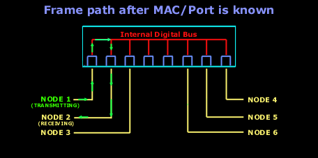
Since the
switch has two MAC addresses in the filtering table, the
devices can make a point-to-point connection and the
frames will only be forwarded between the two devices.
This makes layer-2 switches better than hubs. As we
explained early on this page, in a hub network all
frames are forwarded out to all ports every time. Most
desktop switches these days can hold upto 8000 MAC
addresses in their table, and once the table is filled,
then starting with the very first MAC entry, the switch
will start overwritting the entries. Even tho the number
of entries might sound big .. it only takes a minute or
two to fill it up, and if a workstation dosen't talk on
the network for that amount of time, then chances are
that its MAC address has been removed from the table and
the switch will forward to all ports the packet which
has as a destination this particular workstation.
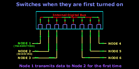
And after
the first frame has been successfully received by
Node 2,
Node 2 sends a reply to
Node 1, check out what
happens:
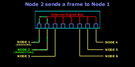
Notice how
the frame is not transmitted to every node on the
switch. The switch by now has already learned that
Node 1 is on the first
port, so it send it straight there without delay. From
now on, any communication between the two will be a
point-to-point connection :
Forward/Filter Decision
When a
frame arrives at the switch, the first step is to check
the destination hardware address, which is compaired to
the forward/filter MAC database. If the destination
hardware address is known, then it will transmit it out
the correct port, but if the destination hardware
address is not known, then it will broadcast the frame
out of all ports, except the one which it received it
from. If a device (computer) answers to the broadcast,
then the MAC address of that device is added to the MAC
database of the switch.
Loop Avoidance (Optional)
It's always
a good idea to have a redundant link between your
switches, in case one decides to go for a holiday. When
you setup redundant switches in your network to stop
failures, you can create problems. Have a look at the
picture below and I'll explain:
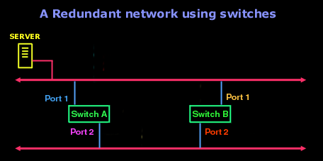
The above
picture shows an example of two switches which have been
placed in the network to provide redundancy in case one
fails. Both switches have their first port connected to
the upper section of the network, while their port 2 is
connected to the lower section of the same network. This
way, if Switch A fails,
then Switch B takes over,
or vice versa.
Things will
work fine until a broadcast come along and causes alot
of trouble. For the simplicity of this example, I am not
going to show any workstations, but only the server
which is going to send a broadcast over the network, and
keep in mind that this is what happens in real life if
your switch does not support
Spanning-Tree Protocol (STP), this is why I stuck
the "Optional" near the
"Loop Avoidance" at the
start of this section:
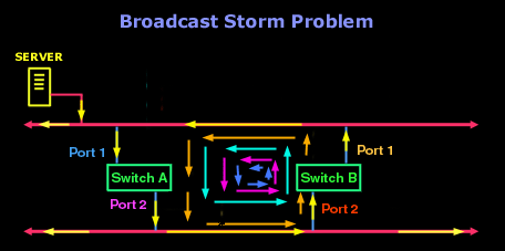
It might
look a bit messy and crazy at a first glance but let me
explain what is going on here.
The Server
for one reason or another decides to do a broadcast.
This First
Round (check arrow) broadcast is sent down
to the network cable and firstly reaches
Port 1 on
Switch A. As a result,
since Switch A has
Port 2 connected to the
other side of the lan, it sends the broadcast out to the
lower section of the network, this then is sent down the
wire and reaches Port 2 on
Switch B which will send it
out Port 1 and back onto
the upper part of the network. At this point, as the
arrows indicate (orange colour)
the Second Round of this
broadcast starts. So again... the broadcast reaches
Port 1 of
Switch A and goes out
Port 2 back down to the
lower section of the network and back up via
Port 2 of
Switch B. After it comes
out of Port 1 of
Switch B, we get the
Third Round, and then the
Fourth Round,
Fifth Round
and keeps on going without stopping.....! This is
what we call a
Broadcast Storm.
A Broadcast
Storm will repeat constantly, chewing up the valueble
bandwidth on the network. This is a major problem, so
they had to solve it one way or another, and they did...
with the Spanning-Tree Protocol
or STP in short. What STP
does, is to find the redundant links, which this case
would be Port 2 of
Switch B and shut it down,
thus eliminating the posibility of looping to occur.
Lan Switch Types
At the
begining of this page we said that the switches are
fast, therefor have low latency. This latency does vary
and depends on what type of switching mode the switch is
operating at. You might recall seeing these three
switching modes at the beginning:
Store & Forward,
Cut-Through and
Fragment
Free.
The picture
below shows how far the different switching modes check
the frame:
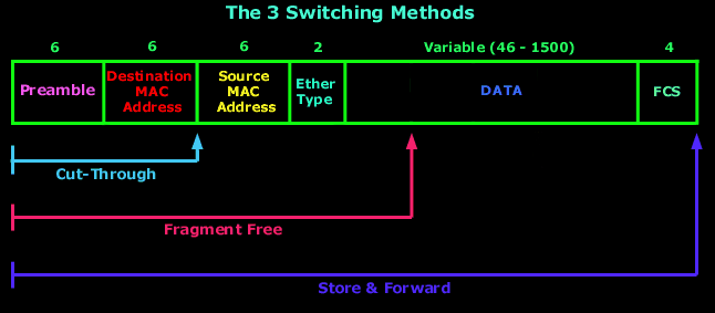
So what
does this all mean ? Switching modes ? I Don't
understand !
Let's Explain!
The fact is
that switches can operate in one of the three modes.
Some advance switches will allow you to actually pick
the mode you would like it to operate in, while others
don't give you any choice. Let's have a quick look at
each mode:
Store & Forward mode
This is one
of the most popular swtiching methods. In this mode,
when the switch receives a frame from one of it's ports,
it will store it in memory, check it for errors and
corruption, and if it passes the test, it will forward
the frame out the designated port, otherwise, if it
discovers that the frame has errors or is corrupt, it
will discard it. This method is the safest, but also has
the highest latency.
Cut-Through (Real Time)
Cut-Through
switching is the second most popular method. In this
mode,the switch reads the frame until it learns the
destination MAC address of the frame it's receiving.
Once it learns it, it will forward the frame straight
out the designated port without delay. This is why we
say it's -Real Time-, there is no delay or error
checking done to the frame.
Fragment Free
The
Fragment free switching method is mainly used to check
for frames which have been subject to a collision. The
frame's first 64 bytes are only checked before
forwarding the frame out the designated port. Reason for
this is because almost all collisions will happen within
the first 64 bytes of a frame. If there is a corruption
in the first 64 bytes, it's most likely that that frame
was a victim of a collision.
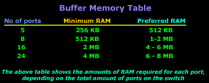
Just keep one important detail in
mind: When you go out to buy a switch, make sure
you check the amount of memory it has. Alot of the cheap
switches which support the Store & Forward mode have
very small amounts of memory buffer (256KB- 512KB) per
port. The result of this is that you get a major
decrease in performance when you have more than 2
computers communicating via that switch cause there
isn't enough memory to store all incoming packets (this
also depends on th swtiching type your switch supports),
and you eventually get packets being discarded.
The table
below is a guide on what amounts of memory you should be
looking at for switches of different configuration :
Bridges
Bridges
are really just like switches, but there are a few
differences which we will mention, but not expand
upon. These are the following:
-
Bridges are software based, while switches are
hardware based because they use an ASICs chip to
help them make filtering decisions.
-
Bridges can only have one spanning-tree instance per
bridge, while switches can have many.
-
Bridges can only have upto 16 ports, while a switch
can have hundreds !
That's
pretty much as far as we will go with the bridges since
they are pretty much old technology and you probably
won't see many around.
|
