Hubs & Repeaters

Introduction

Here we will talk about hubs and explain how they work. In the next section we will move to switches and how they differ from hubs, how they work and the types of switching methods that are available; we will also compare them.

Before we start there are a few definitions which I need to speak about so you can understand the terminology we will be using.

Domain: Defined as a geographical area or logical area (in our imagination) where anything in it becomes part of the domain. In computer land, this means that when something happens in this domain (area) every computer that's part of it will see or hear everything that happens in it.

Collision Domain: Putting it simple, whenever a collision between two computers occurs, every other computer within the domain will hear and know about the collision. These computers are said to be in the same collision domain. As you're going to see later on, when computers connect together using a hub they become part of the same collision domain. This dosen't happen with switches.

Broadcast Domain: A domain where every broadcast (a broadcast is a frame or data which is sent to every comeputer) is seen by all computers within the domain. Hubs and switches do not break up broadcast domains. You need a router to achieve this.

There are different devices which can break-up collision domains and broadcast domains and make the network a lot faster and efficient. Switches create separate collision domains but not broadcast domains. Routers create separate broadcast and collision domains. Hubs are too simple to do either, can't create separate collision or broadcast domain.

Hubs & Repeaters

Hubs and repeaters are basically the same, so we will be using the term "Hub" to keep things simple. Hubs are common today in every network. They are the cheapest way to connect two or more computers together. Hubs are also known as Repeaters and work on the first layer of the OSI model. They are said to work on the first layer because of the function they perform. They don't read the data frames at all (like switches and routers do), they only make sure the frame is repeated out on each port and that's about it.

The Nodes that share an Ethernet or Fast Ethernet LAN using the CSMA/CD rules are said to be in the same collision domain. In plain English, this means that all nodes connected to a hub are part of the same collision domain. In a Collision domain, when a collision occurs everyone in that domain/area will hear it and will be affected. The Ethernet section talks about CSMA/CD and collision domains since they are part of the rules under which Ethernet functions.
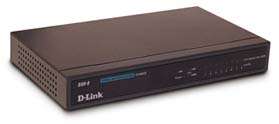
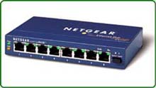
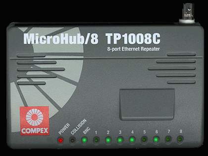
The picture below shows a few hubs : 8 port Netgear and a D-link hub.


The computers (nodes) connect to the hub using Unshielded Twisted Pair cable (UTP). Only one node can be connected to each port of the hub. The pictured hub has a total of 8 ports, which means up to 8 computers can be networked.

When hubs were not that common and also expensive, most offices and home networks use to install coax cable.

The way hubs work is quite simple and straightforward: When a computer on any one of the eight ports transmits data, this is replicated and sent out to the other seven ports. Check out the below picture which shows it clearly.


EXPLANATION:

Node 1 is transmitting some data to Node 6 but all nodes are receiving the data as well. This data will be rejected by the rest of the nodes once they figure out it's not for them.

This is accomplished by the node's network card reading the destination MAC address of the frame (data) it receives, it examines it and sees that it doesn't match with it's own and therefor discards the frame. Please see the Datalink layer in the OSI section for more information on MAC addresses.

Most hubs these days also have a special port which can function as a normal port or as an "uplink" port. An uplink port allows you to connect another hub to the existing one, increasing the amount of ports which will be available to you. This is a cheap solution when you need to get a few more computers networked and it works quite well up to a point.

This is how 2 eight port hubs would look when connected via the uplink port and how the data is replicated to all 16 ports :


In the above picture you can see that Node 1 is again transmitting data to Node 6 and that every other node connected to the hub is receiving the information. As we said, this is a pretty good and cheap solution, but as the network gets busier, you can clearly understand that there is going to be a lot of unecessary data flowing all over the network. All Nodes here are in the same broastcast and collision domain since they will hear every broadcast and collision that occurs.

This is the same situation you get when you use coax cable, where every node or computer is connected onto the same cable and the data that's put onto it travels along the cable and is received by every computer.


You probably also noticed the two orange boxes labled "50 Ohm". These are called terminating resistors and are used on both ends of the coax cable so when the signal gets to them, it's absorbed by them and that way you don't get the signal reflecting back. Think of them as shock absorbent and the data signal is the shock wave which gets absorbed when it reaches the terminating resistors. The coax cable can be up to 185 meters and can contain no more than 30 nodes per segment. What you're looking at in the above picture is one segment 25 meters long with 4 nodes attached to it.

Now coming back to the hubs, there are a few standard features most of them have these include a link and activity LED for each port, a power LED and collision LED. Some hubs have separate link lights and activity lights, others combine them into one where the link light will flash when there is activity, otherwise it remains constantly on. The Netgear hub which is displayed at the beginning of this page has two separate LEDs for the activity and link but the Compex hub below has only one.


This little hub also contains a special BNC connection so you can connect a coax cable to it.

When you do connect it, the BNC light comes on. Notice the label at the top where they have written "8 port Ethernet Repeater".

As we already have said, hubs are just simple repeaters.


The collision light on the hubs will only light up when a collision is detected. Collision is when 2 computers or nodes try to talk on the network at the same time. When this happens, their frames will collide and become corrupted. The hubs are smart enough to detect this and will light up the collision LED for a small amount of time (1/10 of a second for each collision). If you find yourself wondering why couldn't they make things work so more than two computers can talk on the network .. then i would ask you to visit the Ethernet section where all this is explained in detail. Collisions and the fact that only one computer can talk on the network at any given time along with the cabling rules are all part of the Ethernet rules. Remember that any node connected to a hub becomes part of the same collision domain.
Back

Top

Next - Switches & Bridges

  Networking Menu  
    Firewall    
    Networking    
    Cabling    
    Protocols    
    Routing     
    Routers    
    Ethernet      
    Fast Ethernet    
 
   Introduction   
   Introduction   
   Introduction   
   Firewall Topologies   
   Firewall Topologies   
   Firewall Topologies   
   The DMZ Zone   
   The DMZ Zone   
   The DMZ Zone   
   DoS & DDoS Attacts   
   DoS & DDoS Attacts   
   DoS & DDoS Attacts   
   Locking Win9x
   Locking Win9x
   Locking Win9x
   Network Add Translation   
   Network Add Translation   
   Network Add Translation   
 
   Introduction   
   Introduction   
   Introduction   
   The NAT Concept   
   The NAT Concept   
   The NAT Concept   
   The NAT Table   
   The NAT Table   
   The NAT Table   
   Static NAT (Part 1)
   Static NAT (Part 1)
   Static NAT (Part 1)
   Static NAT (Part 2)
   Static NAT (Part 2)
   Static NAT (Part 2)
   Dynamic NAT (Part1)
   Dynamic NAT (Part1)
   Dynamic NAT (Part1)
   Dynamic NAT (Part2)
   Dynamic NAT (Part2)
   Dynamic NAT (Part2)
   Overload NAT/PAT (part1)
   Overload NAT/PAT (part1)
   Overload NAT/PAT (part1)
   Overload NAT/PAT (part2)   
   Overload NAT/PAT (part2)   
   Overload NAT/PAT (part2)   
 
   General   
   General   
   General   
   Data Transmission   
   Data Transmission   
   Data Transmission   
   IP Subnetting   
   IP Subnetting   
   IP Subnetting   
   Supernetting   
   Supernetting   
   Supernetting   
 
   Introduction   
   Introduction   
   Introduction   
   Topologies   
   Topologies   
   Topologies   
 
   Introduction   
   Introduction   
   Introduction   
   Mac Addresses   
   Mac Addresses   
   Mac Addresses   
   Broadcast B   
   Broadcast B   
   Broadcast B   
   Multicast   
   Multicast   
   Multicast   
   Multicast IP List  
   Multicast IP List  
   Multicast IP List  
   Unicast V   
   Unicast V   
   Unicast V   
   Controlling Multicast & Broadcast   
   Controlling Multicast & Broadcast   
   Controlling Multicast & Broadcast   
 
   Introduction   
   Introduction   
   Introduction   
   Basic Concept   
   Basic Concept   
   Basic Concept   
   Subnet Mask Effect   
   Subnet Mask Effect   
   Subnet Mask Effect   
   Subnet Mask Bit   
   Subnet Mask Bit   
   Subnet Mask Bit   
   Subnet Routing & Communications   
   Subnet Routing & Communications   
   Subnet Routing & Communications   
   Subnetting Guidlines   
   Subnetting Guidlines   
   Subnetting Guidlines   
 
   Introduction   
   Introduction   
   Introduction   
   In Depth Analysis   
   In Depth Analysis   
   In Depth Analysis   
   Supernetting Chart   
   Supernetting Chart   
   Supernetting Chart   
   Securing Your Home Network   
   Securing Your Home Network   
   Securing Your Home Network   
 
   Introduction   
   Introduction   
   Introduction   
   UTP CAT 1/2/3/4/5/6 Cable   
   UTP CAT 1/2/3/4/5/6 Cable   
   UTP CAT 1/2/3/4/5/6 Cable   
   UTP Straight Through Cable   
   UTP Straight Through Cable   
   UTP Straight Through Cable   
   UTP X-over Cable   
   UTP X-over Cable   
   UTP X-over Cable   
   Fiber Optic Cable   
   Fiber Optic Cable   
   Fiber Optic Cable   
   10Base T/2/F/5/35   
   10Base T/2/F/5/35   
   10Base T/2/F/5/35   
   100Base T/TX/T4/FX   
   100Base T/TX/T4/FX   
   100Base T/TX/T4/FX   
   Direct Cable Connection (DCC)   
   Direct Cable Connection (DCC)   
   Direct Cable Connection (DCC)   
 
   Introduction   
   Introduction   
   Introduction   
   Serial DCC    
   Serial DCC    
   Serial DCC    
   Parallel DCC   
   Parallel DCC   
   Parallel DCC   
   USB DCC   
   USB DCC   
   USB DCC   
   Important Notes For DCC    
   Important Notes For DCC    
   Important Notes For DCC    
 
   Introduction   
   Introduction   
   Introduction   
   TCP   
   TCP   
   TCP   
   In Depth TCP Analysis   
   In Depth TCP Analysis   
   In Depth TCP Analysis   
   DNS   
   DNS   
   DNS   
   DNS Server Setup (Unix-BIND)   
   DNS Server Setup (Unix-BIND)   
   DNS Server Setup (Unix-BIND)   
   ICMP   
   ICMP   
   ICMP   
   Internet Protocol (IP)   
   Internet Protocol (IP)   
   Internet Protocol (IP)   
   The OSI Model   
   The OSI Model   
   The OSI Model   
 
   Introduction    
   Introduction    
   Introduction    
   A Transport Protocol   
   A Transport Protocol   
   A Transport Protocol   
   Quick Overview    
   Quick Overview    
   Quick Overview    
   TCP Header / Segment   
   TCP Header / Segment   
   TCP Header / Segment   
 
   Introduction    
   Introduction    
   Introduction    
   Source & Destination Port    
   Source & Destination Port    
   Source & Destination Port    
   Sequence & Ack. Numbers   
   Sequence & Ack. Numbers   
   Sequence & Ack. Numbers   
   Header Length    
   Header Length    
   Header Length    
   TCP Flag Options   
   TCP Flag Options   
   TCP Flag Options   
   Window, Checksum, Urgent Flags   
   Window, Checksum, Urgent Flags   
   Window, Checksum, Urgent Flags   
   TCP Options   
   TCP Options   
   TCP Options   
   Data    
   Data    
   Data    
   UDP    
   UDP    
   UDP    
   FTP   
   FTP   
   FTP   
   TFTP   
   TFTP   
   TFTP   
 
   Introduction   
   Introduction   
   Introduction   
   The DNS Protocol   
   The DNS Protocol   
   The DNS Protocol   
   The DNS Resolution Process   
   The DNS Resolution Process   
   The DNS Resolution Process   
   DNS Query Messages   
   DNS Query Messages   
   DNS Query Messages   
   DNS Response Messages   
   DNS Response Messages   
   DNS Response Messages   
 
   Introduction   
   Introduction   
   Introduction   
   The db.domain file   
   The db.domain file   
   The db.domain file   
   The db.addr file   
   The db.addr file   
   The db.addr file   
   Other Common Files   
   Other Common Files   
   Other Common Files   
   Slave DNS Server   
   Slave DNS Server   
   Slave DNS Server   
   DNS Caching   
   DNS Caching   
   DNS Caching   
 
   Introduction    
   Introduction    
   Introduction    
   ICMP Echo/Echo Reply (ping)    
   ICMP Echo/Echo Reply (ping)    
   ICMP Echo/Echo Reply (ping)    
   ICMP Destination Unreachable    
   ICMP Destination Unreachable    
   ICMP Destination Unreachable    
   ICMP Source Quench    
   ICMP Source Quench    
   ICMP Source Quench    
   ICMP Redirect   
   ICMP Redirect   
   ICMP Redirect   
   ICMP Time Exceeded   
   ICMP Time Exceeded   
   ICMP Time Exceeded   
 
   Introduction   
   Introduction   
   Introduction   
   Binary & IP   
   Binary & IP   
   Binary & IP   
   The IP Header   
   The IP Header   
   The IP Header   
   IP Classes   
   IP Classes   
   IP Classes   
 
   Introduction   
   Introduction   
   Introduction   
   Layer 1   
   Layer 1   
   Layer 1   
   Layer 2   
   Layer 2   
   Layer 2   
   Layer 3   
   Layer 3   
   Layer 3   
   Layer 4   
   Layer 4   
   Layer 4   
   Layer 5   
   Layer 5   
   Layer 5   
   Layer 6   
   Layer 6   
   Layer 6   
   Layer 7   
   Layer 7   
   Layer 7   
   Layer Encapsulation & Decapsulation    
   Layer Encapsulation & Decapsulation    
   Layer Encapsulation & Decapsulation    
 
   Introduction   
   Introduction   
   Introduction   
   Routed Protocols   
   Routed Protocols   
   Routed Protocols   
   IP Routing   
   IP Routing   
   IP Routing   
   Routing Protocols   
   Routing Protocols   
   Routing Protocols   
 
   Introduction   
   Introduction   
   Introduction   
   Distance Vector Routing Protocols   
   Distance Vector Routing Protocols   
   Distance Vector Routing Protocols   
   Link State Routing Protocols   
   Link State Routing Protocols   
   Link State Routing Protocols   
   Hybrid Routing Protocols   
   Hybrid Routing Protocols   
   Hybrid Routing Protocols   
   OSPF Routing Protocol   
   OSPF Routing Protocol   
   OSPF Routing Protocol   
   RIP Routing Protocol   
   RIP Routing Protocol   
   RIP Routing Protocol   
   IGRP Routing Protocol   
   IGRP Routing Protocol   
   IGRP Routing Protocol   
   EIGRP Routing Protocol   
   EIGRP Routing Protocol   
   EIGRP Routing Protocol   
   Connectivity Devices   
   Connectivity Devices   
   Connectivity Devices   
 
   Hubs & Repeaters   
   Hubs & Repeaters   
   Hubs & Repeaters   
   Switches & Bridges   
   Switches & Bridges   
   Switches & Bridges   
 
   Introduction   
   Introduction   
   Introduction   
   Cisco Basics   
   Cisco Basics   
   Cisco Basics   
   Cisco Modes   
   Cisco Modes   
   Cisco Modes   
 
   Introduction   
   Introduction   
   Introduction   
   User Exec Mode    
   User Exec Mode    
   User Exec Mode    
   User Privileged Mode   
   User Privileged Mode   
   User Privileged Mode   
 
   Introduction   
   Introduction   
   Introduction   
   Frame Formats   
   Frame Formats   
   Frame Formats   
   Collisions   
   Collisions   
   Collisions   
 
   Introduction   
   Introduction   
   Introduction   
   Ethernet 802.3    
   Ethernet 802.3    
   Ethernet 802.3    
   Ethernet II   
   Ethernet II   
   Ethernet II   
   Ethernet 802.3 SNAP   
   Ethernet 802.3 SNAP   
   Ethernet 802.3 SNAP   
   Ethernet 802.3 Raw (Novell)   
   Ethernet 802.3 Raw (Novell)   
   Ethernet 802.3 Raw (Novell)   
   Media Access   
   Media Access   
   Media Access   
 
   Introduction    
   Introduction    
   Introduction    
   Early Collisions    
   Early Collisions    
   Early Collisions    
   Late Collisions    
   Late Collisions    
   Late Collisions    
   Propagation Delay    
   Propagation Delay    
   Propagation Delay    
   Frame Corruption   
   Frame Corruption   
   Frame Corruption   
   Interframe Gap    
   Interframe Gap    
   Interframe Gap    
   Signal Encoding    
   Signal Encoding    
   Signal Encoding    
 
   Introduction    
   Introduction    
   Introduction    
   10/100 Mbits   
   10/100 Mbits   
   10/100 Mbits   
   Integration   
   Integration   
   Integration   
   Migration   
   Migration   
   Migration   
   The Fast Ethernet Model   
   The Fast Ethernet Model   
   The Fast Ethernet Model   
   Troubleshooting    
   Troubleshooting    
   Troubleshooting