|
TCP
Options
Most of
the TCP Options we will be analysing are required to
appear only during the initial SYN and SYN/ACK phase
of the 3-way-handshake TCP performs to establish a
virtual link before transferring any data. Other
options, however, can be used at will, during the
TCP session.
It is also
important to note that the TCP Options may occupy
space at the end of the TCP header and are a
multiple of 8 bits in length. This means that if we
use one TCP Option that is 4 bits in length, there
must be another 4 bits of padding in order to comply
with the TCP RFC. So the TCP Options length MUST be
in multiples of 8 bits, that is 8, 16, 24, 32 e.t.c
Here's a
brief view of the TCP Options we are going to
analyse:
-
Maximum Segment Size (MSS)
-
Window
Scaling
-
Selective Acknowledgements (SACK)
-
Timestamps
-
Nop
Let's now
take a look at the exciting options available and
explain the purpose of each one.
Maximum Segment Size (MSS)
The
Maximum Segment Size
is used to define the maximum segment that will be
used during a connection between two hosts. As such,
you should only see this option used during the SYN
and SYN/ACK phase of the 3-way-handshake. The MSS
TCP Option occupies 4 bytes (32 bits) of length.
If you
have previously come across the term "MTU"
which stands for
Maximum Transfer Unit, you will be pleased to
know that the MSS
helps define the MTU
used on the network.
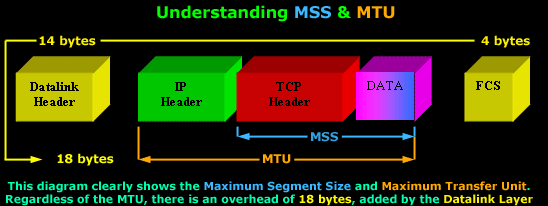
If your
scratching your head because the
MSS and
MTU field
doesn't make any sense to you, or it is not quite
clear, don't worry, the following diagram will help
you get the big picture:

You can
see the Maximum Segment
Size consists of the
TCP Header and
Data,
while the Maximum
Transfer Unit includes the
MSS plus the
IP Header.
It
would also benefit us to recognise the correct
terminology that corresponds to each level of the
OSI Model: The TCP
Header and Data
is called a Segment
(Layer 4), while the IP
Header and the
Segment is called an
IP Datagram
(Layer 3).
Furthermore, regardless of the size the
MTU will have,
there is an additional
18 bytes overhead placed by the
Datalink layer.
This overhead includes the
Source and
Destination MAC Address,
the Protocol type,
followed by the Frame
Check Sequence placed at the end of the
frame.
This is
also the reason why we can only have a maximum
MTU of
1500 bytes.
Since the maximum size of an Ethernet II frame is
1518 bytes, subtracting
18 bytes (Datalink
overhead) leaves us with
1500 bytes to
play with.
TCP
usually computes the
Maximum Segment Size (MSS)
that results in IP Datagrams that match the network
MTU. In
practice, this means the
MSS will have
such a value that if we add the
IP Header as
well, the IP Datagram (IP
Header+TCP
Header+DATA)
would be equal to the network
MTU.
If the
MSS option is
omitted by one or both ends of the connection, then
the value of 536 bytes will be used. The
MSS value of
536 bytes is
defined by RFC 1122 and is calculated by taking the
default value of an IP Datagram, 576 bytes, minus
the standard length of the
IP and
TCP Header (40
bytes), which gives us
536 bytes.
In
general, it is very important to use the best
possible MSS
value for your network because your network
performance could be extremely poor if this value is
too large or too small. To help you understand why,
lets look at a simple example:
If you
wanted to transfer 1 byte of data through the
network, you would need to create a datagram with 40
bytes of overhead, 20 for the IP Header and 20 for
the TCP Header. This means that your using 1/41 of
your available network bandwidth for data. The rest
is nothing but overhead!
On the
other hand, if the MSS is very large, your IP
Datagrams will also be very large, meaning that they
will most probably fail to fit into one packet
should the MTU be too small. Therefore they will
require to be fragmented, increasing the overhead by
a factor of 2.
Window Scaling
We
briefly mentioned Window Scaling in the previous
section of the TCP analysis, though you will soon
discover that this topic is quite broad and requires
a great deal of attention.
After
gaining a sound understanding of what the Window
size flag is used for, Window Scaling is, in
essence, an extention to the Window size flag.
Because the largest possible value in the Window
size flag is only 65,535 bytes (64 kb), it was clear
that a larger field was required in order to
increase the value to a whopping 1 Gig! Thus, Window
Scaling was born.
The
Window Scaling option can be a maximum of
30 bits in size,
which includes the original 16 bit Window size field
covered in the previous section. So that's
16 (original
window field) + 14
(TCP Options 'Window
Scaling') = 30
bits in total.
If
you're wondering where on earth would someone use
such an extremely large Window size, think again.
Window Scaling was created for high-latency,
high-bandwidth WAN links where a limited Window size
can cause severe performance problems.
To
consolidate all these technological terms and
numbers, an example would prove to beneficial:

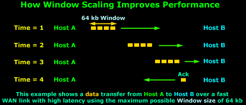
The
above example assumes we are using the maximum
Window size of
64 kbs and because the WAN link has very high
latency, the packets take some time to arrive to
their destination, that is,
Host B. Due to
the high latency, Host
A has stopped transmitting data since there
are 64 kbs of data sent and they have not yet been
acknowledged.
When
the Time = 4,
Host B has
received the data and sends the long awaited
acknowledgement to Host
A so it can continue to send data, but the
acknowledgement will not arrive until somewhere
around Time = 6.
So,
from Time = 1 up
until Time = 6,
Host A is
sitting and waiting. You can imagine how poor the
performance of this transfer would be in this
situation. If we were to transfer a 10 Mb file, it
would take hours!
Let's
now consider the same example, using Window Scaling:

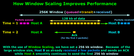
As you
can see, with the use of Window Scaling, the
window size has
increased to256 kb!
Since the value is quite large, which translates to
more data during transit,
Host B has
already received the
first few packets, while
Host A is still
sending the first 256
kb window.
On Time = 2,
Host B sends an
Acknowledgement
to Host A, which
is still busy sending data.
Host A will
receive the
Acknowledgement before it finishes the
256 kb window
and will therefore continue sending data without
pause since it will soon receive another
Acknowledgement
from Host B.
Clearly
the difference that a large window size has made is
evident, increasing the network performance and
minimising the ideal time for the sending host.
The
Window Scale option is defined in RFC 1072, which
lets a system advertise 30-bit (16 from the original
window + 14 from the TCP Options) Window size
values, with a maximum buffer size of 1 GB. This
option has been clarified and redefined in RFC 1323,
which is the specification that all implementations
employ today.
Lastly,
for those who deal with Cisco routers, it may
benefit you to know that you are also able to
configure the Window
size on Cisco routers running the Cisco IOS
v9 and greater. Also, routers with versions 12.2(8)T
and above support Window Scaling, which is
automatically enabled for Window sizes above 65,535
bytes (64 kb), with a maximum value of 1,073,741,823
bytes (1 GByte)!
Selective
Acknowledgments (SACK)
TCP has
been designed to be a fairly robust protocol though,
despite this, it still has several disadvantages,
one of which concerns Acknowledgements, which also
happens to be the reason Selective Acknowledgement
were introduced with RFC 1072.
The
problem with the good old plain Acknowledgements is
that there are no mechanisms for a receiver to state
"I'm still waiting for bytes 20 through 25, but have
received bytes 30 through 35". And if your wondering
whether this is possible, then the answer is 'yes'
it is!
If
segments arrive out of order and there is a hole in
the receiver's queue, then using the 'classical'
Acknowledgements supported by TCP, can only say
"I've received everything up to byte 20". The sender
then needs to recognise that something has gone
wrong and continue sending from that point onwards
(byte 20).
As you
may have concluded, the above situation is totally
unacceptable, so a more robust service had to be
created, hence
Selective Acknowledgments!
Firstly, when a virtual connection is established
using the classic 3-way-handshake the hosts must
send a "Selective
Acknowledgments Permitted" in the TCP Options
to indicate that they are able to use SACK's. From
this point onwards, the
SACK option is sent whenever a selective
acknowledgment is required.
For
example, if we have a Windows98 client that is
waiting for byte 4,268, but the
SACK option
shows that the Windows98 client has also received
bytes 7,080 through 8,486, it is obvious that it is
missing bytes 4,268 through 7,079, so the server
should only resend the missing 2,810 bytes, rather
than restarting the entire transfer at byte number
4,268.
Lastly,
we should note that the SACK field in the TCP
Options uses two 16 bit fields, a total of 32 bits
together. The reason there are two fields is because
the receiver must be able to specify the range of
bytes it has received, just like the example we
used. In the case where Window Scaling is also used,
these 2 x 16 bit fields can be expanded to two 24 or
32 bit fields.
Timestamps
Another
aspect of TCP's flow-control and reliability
services is the round-trip delivery times that a
virtual circuit is experiencing. The round-trip
delivery time will accurately determine how long TCP
will wait before attempting to retransmit a segment
that has not been acknowledged.
Because
every network has unique latency characteristics,
TCP has to understand these characteristics in order
to set accurate acknowledgment timer threshold
values. LANs typically have very low latency times,
and as such TCP can use low values for the
acknowledgment timers. If a segment is not
acknowledged quickly, a sender can retransmit the
questionable data quickly, thus minimizing any lost
bandwidth and delay.
On the
other hand, using a low threshold value on a WAN is
sure to cause problems simply because the
acknowledgment timers will expire before the data
ever reaches the destination.
Therefore, in order for TCP to accurately set the
timer threshold value for a virtual circuit, it has
to measure the round-trip delivery times for various
segments. Finally, it has to monitor additional
segments throughout the connection's lifetime to
keep up with the changes in the network. This is
where the Timestamp option comes into the picture.
Similarly to the majority of the other TCP Options
covered here, the Timestamp option must be sent
during the 3-way-handshake in order to enable its
use during any subsequent segments.
The
Timestamp field consists of a Timestamp Echo and
Timestamp Reply field, both of which the reply field
is always set to zero by the sender and completed by
the receiver after which it is sent back to the
original sender. Both timestamp fields are 4 bytes
long!
Nop
The nop
TCP Option means "No Option" and is used to separate
the different options used within the TCP Option
field. The implementation of the nop field depends
on the operating system used. For example, if
options MSS and SACK are used, Windows XP will
usually place two nop's between them, as was
indicated in the first picture on this page.
Lastly,
we should note that the nop option occupies 1 byte.
In our example at the beggining of the page, it
would occupy 2 bytes since it's used twice. You
should also be aware that this field is usually
checked by hackers when trying to determine the
remote host's operating system.
Summary
This
page provided all the available TCP Options that
have been introduced to the TCP protocol in its
efforts to extend its reliability and performance.
While these options are critical in some cases, most
users are totally unaware of their existence,
especially network administrators. The information
provided here is essential to help administrators
deal with odd local and wan network problems that
can't be solved by rebooting a server or router :)
The
final page to this topic is a summary covering the
previous six pages of TCP, as there is little to
analyse in the data section of the TCP Segment. It
is highly suggested you read it as a recap to help
you remember the material covered.
|
