Network
Topologies
Introduction
Network topologies can take a bit of time to
understand when you're all new to this kind of
cool stuff, but it's very important to fully
understand them as they are key elements to
understanding and troubleshooting networks and
will help you decide what actions to take when
you're faced with network problems.
I will try to be as simple as possible and give
some examples you can relate to, so let's get
stuck right into this stuff !
The Stuff :)
There are two types of
topologies:
Physical and
Logical.
The physical
topology of a network
refers to the layout of cables, computers and
other peripherals. Try to imagine yourself in a
room with a small network, you can see network
cables coming out of every computer that is part
of the network, then those cables plug into a
hub or switch. What you're looking at is the
physical
topology of that network !
Logical
topology is the method used to pass the
information between the computers. In other
words, looking at that same room, if you were to
try to see how the network works with all the
computers talking (think of the computers
generating traffic and packets of data going
everywhere on the network) you would be looking
at the logical part of the network. The way the
computers will be talking to each other and the
direction of the traffic is controlled by the
various protocols (like Ethernet) or, if you
like, rules.
If we used token ring, then the physical
topology would have to change to meet the
requirements of the way the token ring protocol
works (logically).
If it's all still
confusing, consider this: The
physical
topology describes the
layout of the network, just like a map shows the
layout of various roads, and the
logical
topology describes how the data is sent accross
the network or how the cars are able to travel
(the direction and speed) at every road on the
map.
The most common types of
physical topologies, which we are going to
analyse, are: Bus,
Hub/Star
and Ring
The
Physical Bus Topology
Bus topology
is fairly old news and you probably won't be
seeing much of these around in any modern office
or home.
With the
Bus topology,
all workstations are
connect directly to the main backbone that
carries the data. Traffic generated by any
computer will travel across the backbone and be
received by all workstations. This works well in
a small network of 2-5 computers, but as the
number of computers increases so will the
network traffic and this can greatly decrease
the performance and available bandwidth of your
network.

As
you can see in the above example, all computers
are attached to a continuous cable which
connects them in a straight line. The arrows
clearly indicate that the packet generated by
Node 1
is
transmitted to all computers on the network,
regardless the destination of this packet.
Also, because of the way the electrical signals
are transmitted over this cable, its ends must
be terminated by special terminators that work
as "shock absorbers", absorbing the signal so it
won't reflect back to where it came from. The
value of 50Ohms has been selected after
carefully taking in consideration all the
electrical characteristics of the cable used,
the voltage that the signal which runs through
the cables, the maximum and minimum length of
the bus and a few more.
If the bus (the long yellow cable) is damaged
anywhere in its path, then it will most
certainly cause the network to stop working or,
at the very least, cause big communication
problems between the workstations.
Thinnet - 10 Base2, also known as coax cable
(Black in colour) and Thicknet - 10 Base 5
(Yellow in colour) is used in these type of
topologies.
The
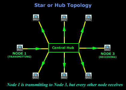
Physical HUB or STAR Topology

The
Star
or
Hub topology
is one of the most common
network topologies found in most offices and
home networks. It has become very popular in
contrast to the bus type (which we just spoke
about), because of the cost and the ease of
troubleshooting.
The advantage of the
star topology
is that if one computer on the
star topology
fails, then only the
failed computer is unable to send or receive
data. The remainder of the network functions
normally.
The disadvantage of using this topology is that
because each computer is connected to a central
hub or switch, if this device fails, the entire
network fails!
A classic example of this
type of topology is the UTP (10 base T), which
normaly has a blue
colour. Personally I find
it boring, so I decided to go out and get myself
green,
red
and
yellow
colours :)
The Physical
Ring Topology
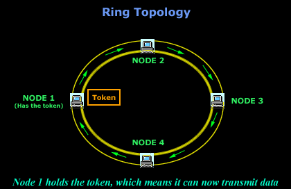
In the
ring topology,
computers are connected on a single circle of
cable. Unlike the bus topology, there are no
terminated ends. The signals travel around the
loop in one direction and pass through each
computer, which acts as a repeater to boost the
signal and send it to the next computer. On a
larger scale, multiple LANs can be connected to
each other in a ring topology by using Thicknet
coaxial or fiber-optic cable.

The
method by which the data is transmitted around
the ring is called
token passing.
IBM's token ring uses this method. A
token is
a special series of bits that contains control
information. Possession of the
token
allows a network device to
transmit data to the network. Each network has
only one token.
The
Physical Mesh Topology

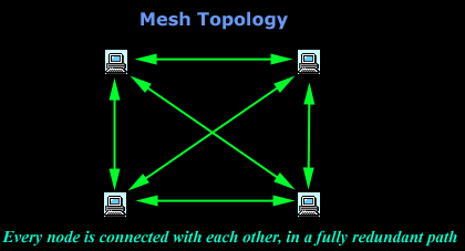
In a
mesh topology,
each computer is connected to every other
computer by a separate cable. This configuration
provides redundant paths through the new work,
so if one computer blows up, you don't lose the
network :) On a large scale, you can connect
multiple LANs using mesh topology with leased
telephone lines, Thicknet coaxial cable or fiber
optic cable.
Again, the big advantage of this topology is its
backup capabilities by providing multiple paths
through the network.
The
Physical Hybrid Topology
With the
hybrid topology,
two or more topologies are combined to form a
complete network. For example, a
hybrid topology
could be the combination
of a star and bus topology. These are also the
most common in use.
