|
T-568A
& T-568B
4-pair Wiring
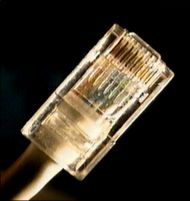
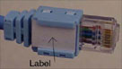
Ethernet is generally carried in 8-conductor cables
with 8-pin modular plugs and jacks. The connector
standard is called "RJ-45" and is just like a
standard RJ-11 modular telephone connector, except
it is a bit wider to carry more pins.
Note:
Keep in mind that the wiring
schemes we are going to talk about are all for
straight through cables only Cross
over
cables
are examined on a separate page !
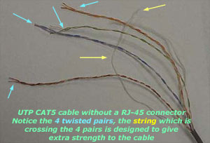
The eight-conductor data cable contains 4 pairs of
wires. Each pair consists of a solid colored wire
and a white wire with a stripe of the same color.
The pairs are twisted together. To maintain
reliability on Ethernet, you should not untwist them
any more than necessary (like about 1 cm). The pairs
designated for 10 and 100 Mbit Ethernet are Orange
and Green. The other two pairs, Brown and Blue, can
be used for a second Ethernet line or for phone
connections.
There are two wiring standards
for these cables, called "T568A"
(also called "EIA") and "T568B"
(also called "AT&T" and "258A"). They differ only in
connection sequence - that is, which color is on
which pin, not in the definition of what electrical
signal is on a particular color.
T-568A
is supposed to be the standard
for new installations, while
T-568B
is an acceptable alternative. However, most
off-the-shelf data equipment and cables seem to be
wired to T568B.
T568B
is also the AT&T standard. In
fact, I have seen very few people using T568A to
wire their network. It's important not to mix
systems, as both you and your equipment will become
hopelessly confused.
Pin Number
Designations for T568B
Note that the odd pin numbers are always the white
with stripe color (1,3,5,7). The wires connect to
RJ-45 8-pin connectors as shown below:
Color Codes for
T568B
Pin color - pair name
1 white/orange
(pair 2)
TxData +
2
orange
(pair 2)
........
TxData -
3 white/green
(pair 3)
..RecvData+
4
blue (pair 1)
5 white/blue
(pair 1)
6
green (pair 3)
...........RecvData-
7 white/brown
(pair 4)
8
brown (pair 4)
The
wall jack may be wired in a different sequence
because the wires are often crossed inside the jack.
The jack should either come with a wiring diagram or
at least designate pin numbers.
Note that the blue pair is on the centre pins; this
pair translates to the red/green pair for ordinary
telephone lines which is also in the centre pair of
an RJ-11. (green=wh/blu; red=blu)
Pin
Number Designations for
T568A
The T568A specification reverses the orange and
green connections so that pairs 1 and 2 are on the
centre 4 pins, which makes it more compatible with
the telco voice connections. (Note that in the RJ-11
plug at the top, pairs 1 and 2 are on the centre 4
pins.) T568A goes:
Color Codes for
T568A
Pin color - pair name
1 white/green
(pair 3)
..RecvData+
2
green (pair 3) ..........RecvData-
3 white/orange
(pair 2)
TxData +
4
blue (pair 1)
5 white/blue
(pair 1)
6
orange
(pair 2)
.........TxData
-
7 white/brown
(pair 4)
8
brown
(pair 4)
The diagram below shows the
568A
and
568B
in comparison:
Where are
they used ?
The most common application for a straight through
cable is a connection between a PC and a hub/switch.
In this case the PC is connected directly to the
hub/switch which will automatically cross over the
cable internaly, using special circuits. In the case
of a CAT1 cable, which is usually found in telephone
lines, only 2 wires are used, these do not require
any special cross over since the phones connect
directly to the phone socket.

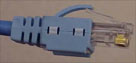
The picture above shows us a
standard CAT5 straight thru cable, used to connect a
PC to a HUB. You might get a bit confused because
you might expect the
TX+ of one side to
connect to the TX+
of the other side but this is
not the case. When you connect a PC to a HUB, the
HUB it will automatically x-over the cable for you
by using its internal circuits, this results
Pin 1
from the
PC
(which is
TX+)
to connect to Pin 1
of the
HUB
(which connects to
RX+).This
happens for the rest of the pinouts aswell.
If the
HUB
didn't x-over the pinouts
using its internal circuits (this happens when you
use the Uplink port on the hub) then
Pin 1
from the
PC
(which is
TX+)
would connect to Pin 1
of the
HUB
(which would be
TX+
in this case). So you notice that no matter what we
do with the HUB
port (uplink or normal), the
signals assigned to the
8 Pins
on the
PC
side of things, will always
remain the same, the HUB's pinouts though will
change depending wether the port is set to normal or
uplink.
This pretty much concludes our discussion on
straight thru UTP cables !
|


 .......
 ........